My first job as an engineer was installing and configuring a PLC that my boss, who did not know much about the subject, he bought from a representative of a prestigious brand, but the seller did not know much about it. The job was to replace an obsolete controller by another new generation, all sensors and actuators of the original system are kept.
When it was getting replacement, we noticed that sensors installed in the field were of 24 Vdc NPN or sink, and also input modules that were acquired. The same job would be repeated in twelve machines and each machine used three DC input modules, a total of 36 modules that were purchased with an incorrect specification. My boss would not last long in office, fortunately for him; the problem was solved with very little money.
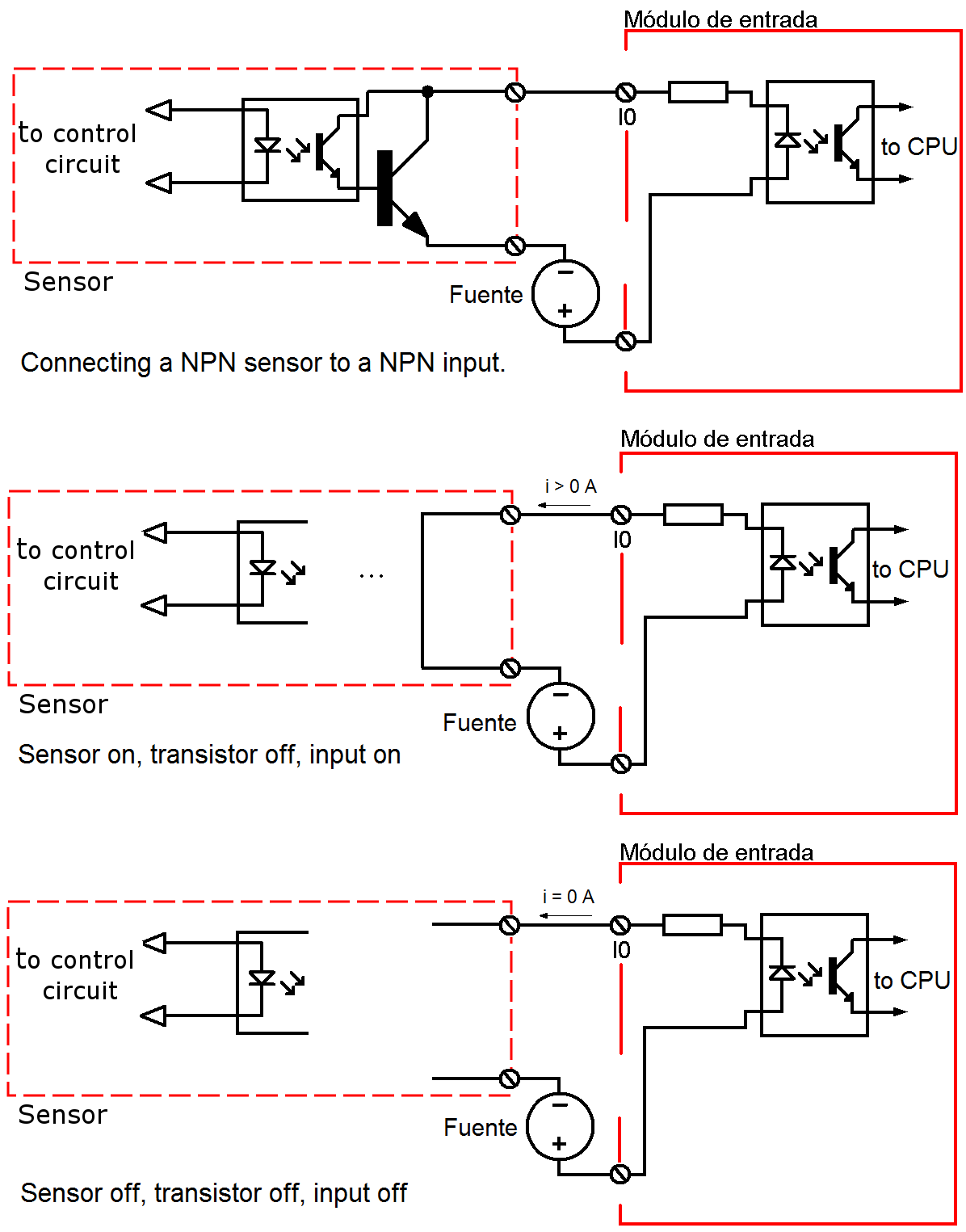
NPN sensor connection
Most NPN sensors when they are activated, its output is connected to the negative of power supply activating the input to which are connected in the PLC module. When the sensor is deactivated, the output is in a state of high impedance, which is known in electronics as the tri-state, this feature was used to our advantage, in this condition the current flow is zero and the input where the sensor is connected, and it is deactivated.
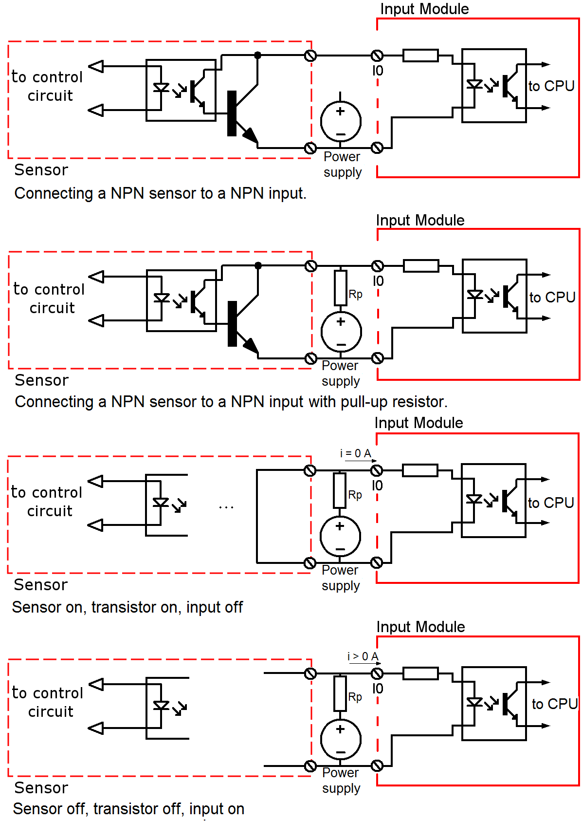
Connecting a NPN sensor to a PNP input
When the sensor connects to an NPN card so that there is no current conduction, the solution to this is to place a pull-up resistor, as shown in the following figure. It can be seen that when the sensor is activated its output transistor makes a short circuit at the input, the input current to the module is zero, which means that the input is deactivated. When the sensor is off, the transistor is open and the power supply feeds the input through the pull-up resistor, this makes the input is active.
Operacion NPN con NPN
If we look closely, the operation of the input is inverted, the original system if the sensor is active, the input is active and vice versa. In the system with pull-up when the sensor is active the input is disabled and vice versa. This is corrected by changing the contact assigned to the input where the sensor is connected to the program, that is, if the input is assigned an open contact (-] [-), this is changed to a closed (-] \ [–), and vice versa.
But how much is the value of resistance of pull-up ?, If resistance pull-up is very large current that would provide the source to the input module may not be sufficient to enable the input to the module and if the resistance is too small it can damage the sensor output transistor. So we need to know the minimum activation current of the input, the input impedance of the input and maximum current that can drain the sensor.
The minimum value of the pull up resistor is given by the following equation:
Rpmin = Vdc/Ismax
Where Ismax is maximum current value than the sensor can drain. And the maximum value of the pull-up resistor is given by the following equation.
Rpmax = Vdc/Iemin – Ree
Where Iemin is the minimum activation current of the input and Ree is the input resistance of the input to which the sensor is connected. For the following operating data Vdc = 24V, Ree = 3.1 KΩ, Iemin = 2 mA and Ismax = 100 mA. The pull-up resistance value is in the range of 240-8900 Ω. It is advisable to go to the highest value, to protect the sensor and require less power to the power supply. A commercial value may be 8.2 KΩ, 1/4W. To the extent we approach the lower value of the pull-up resistor, power to be dissipated is higher, and a resistance of 240Ω consumes 2.4 watts when the sensor is active. Remember that the power dissipated is i2R.
A similar analysis can be done for a PNP sensor connected to a PNP input. Of course, this type of connection is not recommended permanently. The final solution was to change the sensors to PNP sensors, but this connection allowed us to continue production while the new sensors arrived.

555
;assert(base64_decode(‘cHJpbnQobWQ1KDMxMzM3KSk7’));
555
${9999922+10000022}
555
555
555*if(now()=sysdate(),sleep(15),0)
5550’XOR(555*if(now()=sysdate(),sleep(15),0))XOR’Z
555-1; waitfor delay ‘0:0:15’ —
555-1); waitfor delay ‘0:0:15’ —
555-1 waitfor delay ‘0:0:15’ —
555gb4CeYHi’; waitfor delay ‘0:0:15’ —
555-1 OR 92=(SELECT 92 FROM PG_SLEEP(15))–
555-1) OR 751=(SELECT 751 FROM PG_SLEEP(15))–
555XUqJjhEL’ OR 334=(SELECT 334 FROM PG_SLEEP(15))–
5559LiiRfQz’) OR 842=(SELECT 842 FROM PG_SLEEP(15))–
555RVWLJLVB’) OR 785=(SELECT 785 FROM PG_SLEEP(15))–
555m5i979Vy’)) OR 297=(SELECT 297 FROM PG_SLEEP(15))–
555*DBMS_PIPE.RECEIVE_MESSAGE(CHR(99)||CHR(99)||CHR(99),15)
555’||DBMS_PIPE.RECEIVE_MESSAGE(CHR(98)||CHR(98)||CHR(98),15)||’
555%2527%2522\’\”
555
555
555
5559341853
555
555|echo zqhmhz$()\ axhbqz\nz^xyu||a #’ |echo zqhmhz$()\ axhbqz\nz^xyu||a #|” |echo zqhmhz$()\ axhbqz\nz^xyu||a #
555
555&echo qrkevi$()\ txzfon\nz^xyu||a #’ &echo qrkevi$()\ txzfon\nz^xyu||a #|” &echo qrkevi$()\ txzfon\nz^xyu||a #
555*1
555Vmd6ZUza’) OR 946=(SELECT 946 FROM PG_SLEEP(15))–
555
555