The cross reference is used to quickly locate items within the set of drawings, especially those elements whose parts are in different drawings.
Grid location. Cross reference
To find the elements in the drawing a coordinate system based on letters and numbers are used. This method is called the grid method in which the sheet is divided into areas identified by letters placed from top to bottom on the side edge of the paper and numbered serially arranged from left to right at the top and lower margins. The following example illustrates this:
A Contactor for an electric motor must be wired to both the motor and the corresponding output of a PLC, but for the purposes of drawings, the output module and the motor does not appear in the same plane, one plane corresponds to outputs and the other to the power, so that the equipment must be referenced. In Figure 1, the contactor coil and beside all contacts associated with this coil appear, as you can see, the main contacts (terminals 1-2, 3-4, 5-6) have the reference 01/2C aside; the number 01 is the number of the drawing and 2C code correspond to the coordinates of the element, in Figure 2 you can see the drawings 01 with emphasis on the part of the searched item. We can verify that this is the same element because the name KM101 is the same for both parties. In this case, the letters KM nomenclature correspond to the class K for contactor, M for motor and 101 is the number of the element.
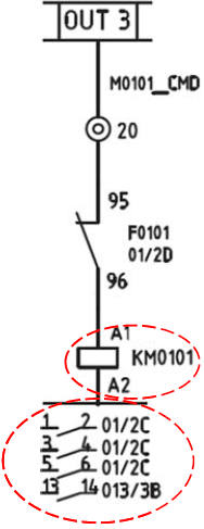
Figure 1. Cross reference
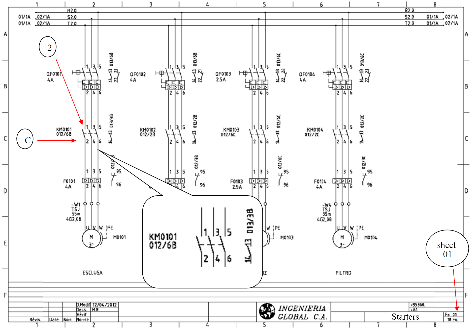
Figure 2. Referenced elemet. Grid location.
Band location
The band location is similar to the grid location. The cross reference 01/2C (of the grid) is replaced by the reference 1.7, to indicate the same element in Figure 3, where 1 is the number of the drawing and number 7 corresponds to the band.
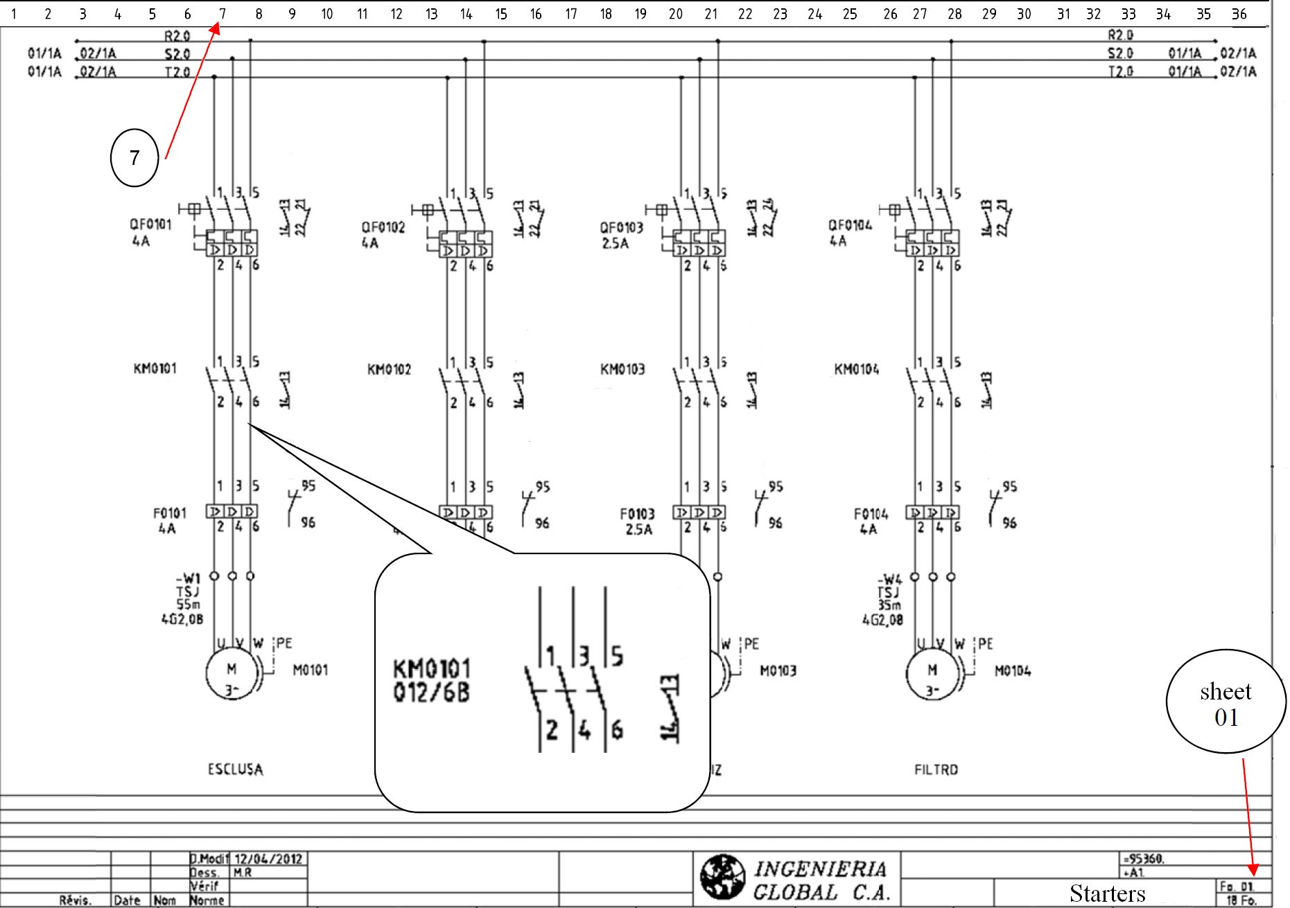
Figure 3. Referenced Element. Band location.
Line location
In the figure below you can see how the contact KM01 on line 1.5 reference to the line 1.7, which contains the coil of this contact.
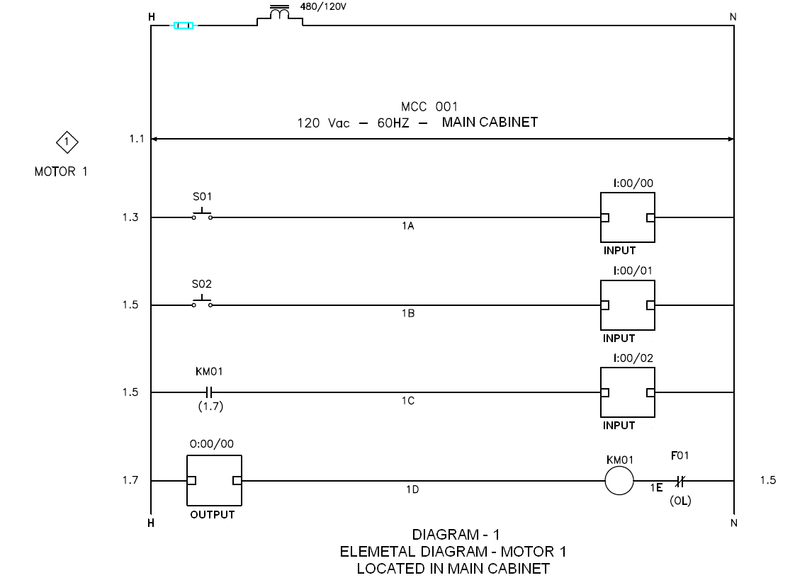
Figure 4. Referenced element. Line location.