The processes have continuous variables that belong to state space of real numbers, that is to say, they can have infinity values when they change over time. On the other hand, the digital systems, manufactured by the humans, as for example the controllers and the personal computers among others, working with discrete signals expressed in binary numbers, called digital signals and that for reason of physical limitations in the development of the electronics devices, belong to a finite state space, this is, the variables can have only a finite number of values through of the time. Also, an analog variable is defined as, those that have two or more values, in this sense, the continuous signals are analog signals and discrete signals that have two or more bit are analog signals too.
Seen from the controller, the analog variables come from the transmitter. They converted a physic variable (for example, temperature, pressure, flow, level, so on) to a standard analog electric variable (for example, 4 to 20 mA) to be transmitted. The transmitted signals must be processed by the controllers, therefore, they are converted from analog to digital, and this is done with an analog to digital converter (ADC) in the input analog module. As is logical, for to do the inverse operation, this is to say, to convert a digital signal to analog signal, it is done using a digital to analog converter (DAC) located in the output analog module. There are several types of ADC, such as successive-approximation, delta-sigma modulation and flash, among others. There are two characteristics of the ADCs that stand out, the bit number and the conversion time. The best ADCs have a high bit number and a small conversion time.
Quantization
The bit number gives way to another concept called quantization. The quantization is the process that allows representing a signal that belongs to the continuous state space with another that belongs to the discrete state space. For example, if it want to convert a continuous signal that varies between 0 y 10 VDC (note between 0 y 10 VDC there are infinite values) with a 8 bit ADC (note only 256 (28) numbers can be represented with 8 bit, which is a finite number), the binary number in the output of ADC goes from 0 to 255 (28-1), where, as is logical, the value 0 in the digital signal is corresponding to 0 volt en the continuous signal and the value 255 in the digital signal is corresponding to the value 10 volts in the continuous signal, the rest of the values are distributed from 0 with a increment of V/(28-1) = 10/255 = 39,215mV, which is the converter resolution, if the bit number is greater, the converter resolution is less. The next table shows the first and the last digital values with their corresponding continuous values.
Digital value Continuous value
0 0
1 0,03921569
2 0,07843137
3 0,11764706
…
253 9,92156863
254 9,96078431
255 10
SAMPLE
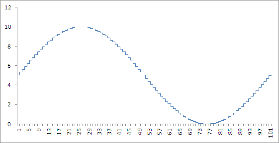
The conversion time is related to the time in that the sample of analog signal is taken, sometimes it want to convert more than one continuous signal with only one converter, the multiplexers are used for that. The multiplexers share the ADC among the signals to convert. Each time that a conversion of the continuous signal is done, it is said that a sample has been taken. The time between two samples is called sample time or sample period. While the sample time is shorter, the digital signal looks more to continuous signal and the error is smaller. The next figure shows an analog signal converted to digital with: (a) 8 bits and 100 samples in a period (b), 8 bits and 40 samples (c), 4 bits and 100 samples, (d) 4 bits and 40 samples and (e) the continuous signal.
8 bit, 100 samples8 bit, 40 samples
4 bit, 100 samples
4 bit, 40 samples
Continuous signal
The available analog modules use 12-bit converter or more, with conversion times of the order of milliseconds or less. The next figure shows the signal different types.
Signal


