Operator interface

What is an operator interface?

An operator interface is a device (or more) by which the operator gives orders to the controller of a process and receives from the controller the process current state.
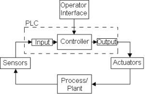
Operator interface

Operator interface

Operator interface levels

There are a variety of ways in which they can implement an operator interface. In its simplest form consists of buttons, switches and thumbwheel switches connected to the inputs of the controller; and pilot lights and BCD indicators connected to the outputs. The operator gives orders to the controller through input devices and gets the state through devices connected to the outputs.
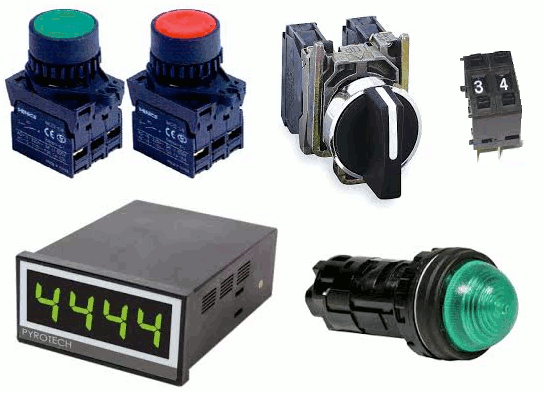
Buttons and lights

Buttons and lights

Another level of operator interface are alphanumeric devices, keyboards and screens, some devices bring integrated the keyboard and the screen. The operator provides the information through the keyboard with a string of alphanumeric characters or assigning a specific action to a key, such as start or stop of an electric motor. The controller shows the process status via messages on the screen. Alphanumeric devices are connected to the controller via serials networks.

Alphanumeric devices

Alphanumeric devices

The next level is the graphics operator panels, which are electronic devices that can run a file created on a PC and downloaded to the panel via of a network. The file usually contains screens and these in turn contain controls such as buttons, numeric inputs, alphanumeric inputs, numeric displays and alphanumeric displays among other, in summary, everything that is done with the two previous levels can be done with a graphic panel and many other things like alarms, trends, messages. Examples of these panels are Panel View of Rockwell Automation and Magelis of Schneider Electrics.
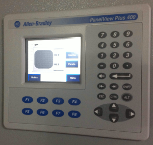
Graphic panel

Graphic panel

The most advanced level of operator interface are computers, these differ from panels that have a hardware with the ability to run more advanced operating systems and much larger memory capacities, allowing execute files with more and better features. Of course, the computer must be running the application that execute these files, these software are called HMI (human machine interface). Examples of such software are FactoryTalk View Site Edition of Rockwell Automation and Woderware InTouch of Schneider Electric.
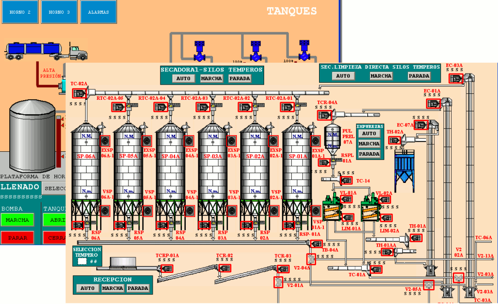
HMI Software

HMI Software

In general, the operator interface of an industrial process will be formed by combining several of devices mentioned above.

4 Comments

  1. excepturi et sed ex eligendi. est sapiente architecto deleniti ex ut omnis sed et ab repellat veritatis est perferendis occaecati dignissimos consectetur ullam ut rerum occaecati eos atque deserunt. r

    Reply
  2. deleniti eligendi odit molestiae ut veritatis quia voluptatibus. necessitatibus eligendi atque corporis. fuga officiis molestiae dolorem placeat recusandae reiciendis voluptas a nisi impedit consequat

    Reply
  3. wetzelmhoonjgq1a2+636om7crsapj@gmail.com

    illo eligendi dolore ut hic eos tenetur explicabo accusamus. dignissimos eum magnam suscipit deserunt ut laboriosam accusantium quas non iste rerum recusandae.

    Reply
  4. JeremyMap

    mulcher rotor balancing

    Mulcher Rotor Balancing: A Comprehensive Guide
    Mulcher rotor balancing is a crucial process aimed at optimizing the performance of mulching equipment. Proper balancing not only minimizes vibrations and noise during operation but also prevents premature wear of bearings, mitigates the load on the drive system, and ultimately extends the lifespan of the machinery. This guide details the steps involved in balancing a mulcher rotor using the Balanset-1A portable balancer, designed for efficient, onsite use without the need for dismantling the equipment.

    Understanding the Importance of Rotor Balancing
    Rotors in mulchers can become unbalanced due to various factors, including uneven wear or manufacturing discrepancies. This imbalance can lead to increased vibration levels, which may result in mechanical failures, noise disturbances, and decreased efficiency. Therefore, balancing the rotor is imperative for maintaining optimal operation and prolonging the life of your mulcher.

    Preparation for Balancing
    The preparation phase is an essential step before initiating the balancing process. Here’s what you need to do:

    Conduct a thorough inspection of the mulcher’s components, paying close attention to the bearings and ensuring they are free from play.
    Inspect the housing structure for any signs of cracks or damage that could impact performance.
    Ensure that all bolted connections are tightened appropriately, as loose connections may lead to further imbalances.
    To eliminate potential interferences during the balancing process, it may be beneficial to either weld the push frame and front curtain to the mulcher body or completely remove them.

    Step-by-Step Balancing Process
    Once the preparation is complete, follow these steps to effectively balance the rotor using the Balanset-1A portable balancer:

    Setup Vibration Sensors: Place the vibration sensors perpendicularly to the rotor’s axis of rotation. Ensure that the tachometer is secured on a magnetic stand for stable positioning.
    Apply Reflective Tape: Install reflective tape on the pulley or rotor, ensuring the rotation sensor can easily detect it during operation.
    Connect Devices: Hook the sensors up to the Balanset balancer and connect it to a compatible laptop for data analysis.
    Configure the Software: Open the Balanset software, configure it for two-plane balancing, and enter the necessary rotor data required for accurate analysis.
    Initial Measurement: Start the rotor and record the initial vibration levels to establish a baseline for the balancing process.
    Calibration Weight Placement: Position the calibration weight in the first plane corresponding to the first sensor’s location. Take the measurement and make note of the readings.
    Weight Adjustment: Transfer the calibration weight to the second plane, aligning it with the second sensor to capture the required data.
    Data Analysis: Allow the software to process the data from the initial measurements. The system will suggest the amount of corrective weight needed and at what angle it should be placed for optimal balancing.
    Installing Corrective Weights: After removing the calibration weight, install the recommended corrective weights in accordance with the software indications.
    Final Spin Measurement: Conduct a final spin of the rotor to verify the success of the balancing process. Adjust further if the software indicates that additional corrections are necessary.

    Components of the Balanset-1A
    The Balanset-1A is a comprehensive tool specifically designed for rotor balancing, featuring a range of essential components that facilitate the entire process:

    Control Interface Unit: This unit acts as the central processing unit, managing sensor signals and overseeing the entire balancing operation.
    Vibration Sensors: These highly sensitive sensors ensure precise measurement of vibrational parameters, essential for accurate balancing outcomes.
    Optical Sensor (Laser Tachometer): Utilizes a contactless method to measure the rotor’s rotation frequency, providing high accuracy necessary for effective balancing.
    Magnetic Stand: Ensures the secure placement and precise adjustment of the optical sensor during measurements.
    Electronic Scales: Allows for meticulous weighing of the corrective weights before installation, a critical factor for effective balancing.
    User-Friendly Software: The specialized software linked to the Balanset-1A simplifies the data entry process, analysis, and calculation of corrective weights for the balancing procedure.
    Protective Transportation Case: Safeguards the equipment from damage during transport and storage, ensuring longevity and reliability.

    Conclusion
    Mulcher rotor balancing is an indispensable maintenance process that enhances the efficiency and durability of the equipment. By following the outlined steps using the Balanset-1A balancer, operators can experience significant improvements in performance, reduce wear and tear, and increase the operational lifespan of their mulching machinery. Investing time in proper balancing will lead to a smoother and more effective operation, ultimately resulting in reduced downtime and maintenance costs.

    Reply

Leave a Comment

Your email address will not be published. Required fields are marked *