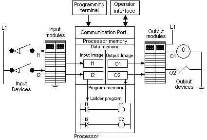
The processor or CPU is the more important part of the controller; it is the responsible for executing all tasks for which it was schedule through instructions and data that are locate in the memory. The controller memory is split into data memory and program memory
Data memory
All variables that the processor uses are located into a memory area called data memory. These variables are updated by the program in the controller or come from outside through I/O modules or networks connected to operator interfaces or to others controllers. Into the data memory is the input memory, where the state of the digital and analog input modules is stored and the output memory where the state of digital and analog output modules are stored.
Booleans, integers, float points and strings are among the data types that are stored into data memory. Some controller instructions use a more complex data structure as the timers and the counters. For example, the timer, at least need an integer for the final value, an integer for the current value and a Boolean for indicate that the current value reached the final value. In some processors, the three variables are grouped into one variable, which is used with the timer instruction. If the instructions set of the controller have instructions more complex, there are more data types that are stored in the data memory.
Program Memory
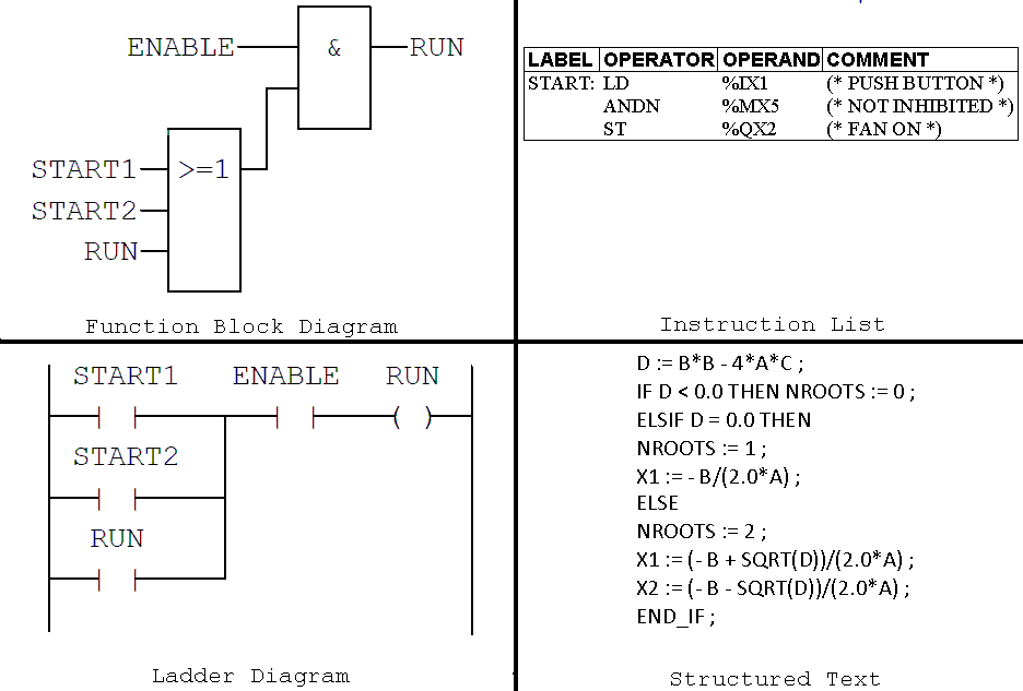
Instructions are put in ordered way into the routines to indicate the actions that the controller is going to execute. The way to put the instructions is depending of the type of language used. The IEC 61131 standard indicate 4 type of the language, these are: Instruction List (IL), Structured Text (ST), Ladder Diagram (LD) and Function Block Diagram (FBD). Moreover, the same standard includes the special function chart, which is a way to organize the routines based in Petri nets.
Both data memory and program memory are preserved with a battery or capacitor, such a way that in absent of electric energy, neither data nor the program are lost. The controller has at least a communication port which is used for download the program and the data.
Scan Cycle
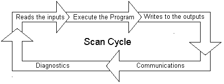
The execution of operations for which the controller is programmed occurs as follows:
- Read the input. The input state is read from input module and it is stored in the input memory.
- Scan program. All routines in the controller are executed and the data memory is updated.
- Write to the output. The information in the output memory is writes to the output modules.
- Process any communications requests
- Verify if the processor is working correctly.
This sequence of operations is called scan cycle. A watchdog time can be configured, the time of the scan cycle must be less than watchdog time otherwise an error will be occur.
In the PLCs more advanced, the operations of scan cycle do not occur in sequential way, each operation is executed cyclically in periods of time, in independent way. Some operations can be executed when events occur.


