The timer is a output instruction, therefore, placed in the last position of the line. There are three types of timers: on delay (TON), off delay (TOF) and on delay retentive (RTO). Each timer has a time base that can be 1ms, 10ms or 1 sec for the MicroLogix 1100 family.
Timer memory element
The default file of Allen Bradley Micrologix 1100 timers is T4. You can create more timer files from the file 9 to 255. Each element of the data memory assigned to the timers consists of three 16-bit integers, an integer for the preset (PRE), an integer for the accumulated value (ACC) and the last integer only three bits are used, they are called enabled (EN), timer timing (TT) and done (DN). The parts of each element for the TON instruction are described.
Preset value. The preset value is multiplied by the time base to specify the time delay. The address for the preselected values is as follows: T#file: #element.pre, for example T4: 0.pre. You can also know the value of any of 16 bits of preset adding to the address /#bit at the end, for example T4: 0.pre/5 refers to bit 5 of the preset value of the first element of T4 file.
Accumulated value. The accumulated value specifies the time from the moment that bit enabled is set to the current time. The accumulator address is as follows: T#file: #element.acc, for example T4: 0.ACC. You can also know the value of any of the 16 bit of accumulator value adding to the address /#bit at the end, for example T4: 0.ACC / 5 refer to bit 5 of the accumulator of the first element of T4 file.
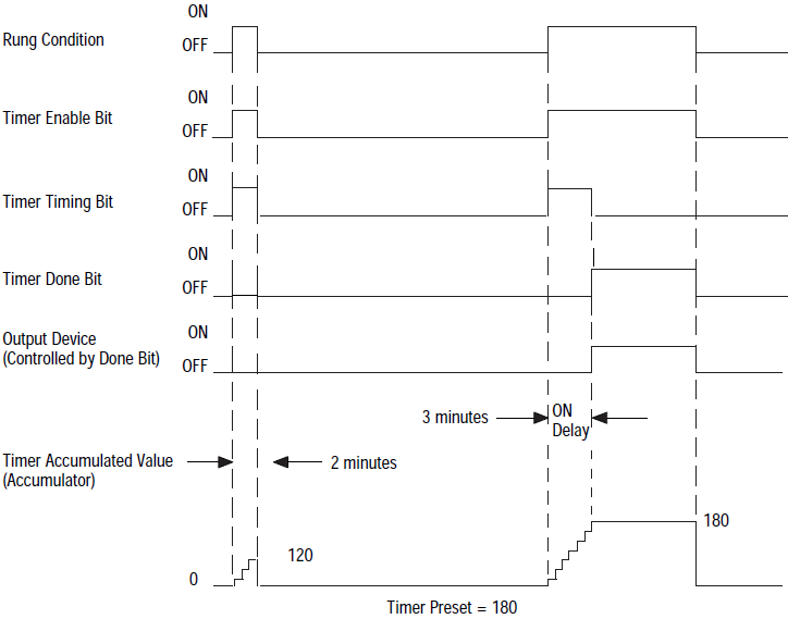
Bit Enable. It set when the line is true, indicates that the timer is enabled. The address for these bits is as follows: T #file: #element / EN, for example T4:0/EN.
Bit timer timing. It set in the time interval that occurs between the bit enable is and when the accumulated value is equal to the preset value. The address for these bits is as follows: T#file: #element/TT, for example T4:0/TT.
Bit Done. It set if the accumulated value is equal to the preset value and the timer is enabled. The address for these bits is as follows: T#file:#element/TT, for example T4: 0 / TT.
When the timer is disabled, all integers and bits of the element are cleared. The following timing diagram illustrates the operation.


