Previously we talked about the timer on delay; now talk about timer off delay (TOF). At the end of the post it will show an example of a level control of a tank using timers.
The timer is an output instruction, therefore, is placed in the last position of the line. Each timer has a time base that can be 1ms, 10 ms or 1 s for the MicroLogix 1100 family.
Timer off delay memory element
All timers (on delay, off delay and retentive) of this family of processors share the same memory files. The timers default file of Allen Bradley MicroLogix 1100 is T4. Each element of the data memory assigned to timers consists of an integer to the preset value (PRE), an integer for the accumulated value (ACC) and three bits, called enable (EN), timer timing (TT) and done (DN). The following describes the operation of each element for TOF.
Preset value is multiplied by the time base of the timer to specify the time delay. The address for the preselected values is as follows: #file: #element.pre, eg T4: 0.pre.
Accumulated value specifies the time from the moment that was disabled up to the current moment. The address is for accumulators as follows: T #file:#element.acc, eg T4: 0.ACC.
Enabled bit is set when the line is true, indicates that the timer is enabled. It is clear when the line is false. The address for these bits is as follows: T #file: #element/EN, for example T4: 0 / EN.
Timing timer bit is set in the time interval that occurs between the timer is disabled and when the accumulated value reaches the preset value. The rest of the time this bit is clear. The address for these bits is as follows: T #file:#element/TT, for example T4: 0 / TT.
Done bit is set when the accumulated value is equal to the preset value and the timer is disabled. It is clear when the timer is enabled. The address for these bits is as follows: T #file:#element/TT, for example T4: 0 / TT.
The following timing diagram illustrates the operation of the timer.
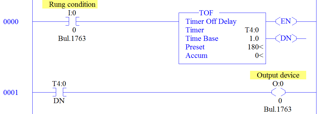
Timer off delay
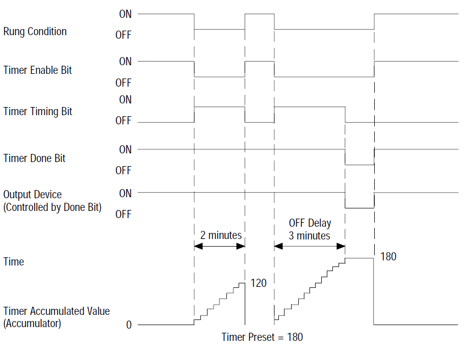
Timing diagram. Timer off delay
Tank level control
The following example illustrates how to do a simple level control. For this, a capacitive sensor is placed in the input I: 0/5 which detects the presence of liquid in the tank and on-off valve used to fill the tank at the output O: 0/0. The control algorithm is very simple, when the sensor is deactivated the valve is open and when the sensor detects product the valve is closed. First, the control is made without the use of timers and the valve opens and closes very quickly, reducing their lifespan. Timers are then placed to improve performance. In the following video you can see this process.