In the electrical drawings are represented graphically the components and their interconnection in an electrical installation. The use of electric drawings is based on standards developed by different international organizations. Its use permits the construction and maintenance of electrical systems, in addition to representing the operation thereof.
Standardization organizations
To ensure proper information flow and readability of electrical drawings are designed various standardization organizations and standards worldwide within which highlights:
- American National Standards Institute (ANSI)
- Deutsches Institut für Normung (DIN)
- International Organization for Standardization (ISO)
- International Electrotechnical Commission (IEC)
- National Electrical Manufacturers Association (NEMA)
Symbols
It is the graphical representation of a physical element, present in an electrical drawings, such as a relay, a motor starter, or a transformer among others. There are different symbols for the same device according to the standard being used to develop the electrical drawings. Different symbols to DIN, ANSI and IEC standards are shown here.
Tags
In an electrical diagram for each symbol is associated with a Tag (name) which will identify the device within the set of drawings, other documents associated with the system and the device itself once it is installed in the field. There are many ways to choose the tag, and depends on the designer, two ways are frequently used will be explained.
Way 1: The tag for the symbol consists of two parts, the class and the number. For example the initials in Q3, Q refers to a protection switch and numeral 3 is used to distinguish if there are several protections. Often it combine more than one letter for the class, for example the letter K refers to a relay or a contactor (starter) if combined with the letter M then KM refers to the contactor (starter) of a motor. According to the standard IEC750 the tag must begin with a hyphen, for example -Q3A.
Way 2: The tag for the symbol consists of three parts: drawing number, class and location in the drawing. For example 1Q15 refers to a protection switch located in the plane 1 band 15 (the drawings are often divided into bands or squares to help find elements). In a variant of this, the location in the drawing is changed by consecutive numbers, for example if there are two protection switches in drawing No. 1; their tags would be 1Q1 and 1Q2.
A continuación se muestra la tabla para las letras que se usan en la clase.
Here are the tables for the letters used in the class and function respectively.
Types of electrical drawings
The electrical drawings describing different aspects of systems and are generally grouped into related or similar elements. We can find the following types of electrical drawings on the same set of diagrams.
- General supply.
- Power
- Commad
- Input and output.
- Equipment supply
- Terminal blocks.
- Cabinet
- Network
A more detailed description of the types of plans and examples can be found here.
Formats
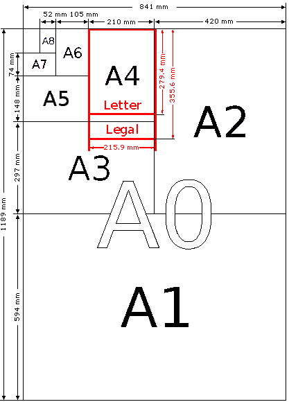
When an electrical drawings is performed; one of the aspects to be taken into account is the size of paper used; generally, the drawing is set to the most comfortable size for the end user. The following table shows the formats used for drawings, the dimensions of each of the formats and margins must have. These dimensions have been taken from DIN and its use has been generalized worldwide, the following figure shows a scheme where you can see the different formats.
|
FORMAT |
DIMENSIONS (mm) |
MARGINS |
|
|
LEFT |
OTHRES |
||
|
A0 |
1189X841 |
35 |
10 |
|
A1 |
594X841 |
30 |
10 |
|
A2 |
420X594 |
30 |
10 |
|
A3 |
297X420 |
30 | 10 |
|
A4 |
210X297 |
30 |
10 |
Formats
The drawing also has a letterhead, coordinates and a logo.
Letterhead:
On the letterhead all the information regarding the electrical diagram is placed, this includes:
- Date of the version.
- Date Modified.
- Name of the sketcher.
- Scale
- Revision number.
- Description of the drawing.
- Number of drawing.
- Total number of sheet having the set of drawings.
- Company name where the electrical system is.
- Name of the company that developed the drawing.
Its location is usually at the bottom of the drawing, although it can also be placed on the left or right.
Logo:
This section is optional and corresponds to logo of the company that designed the drawing
Coordinates:
It helps to quickly find a specific element in a drawing that is referenced in another drawing; for this, the drawing is divided into squares or strips. In this system it is also called cross-reference.
Squares division: uses numbers on the horizontal edges and letters on the vertical edges, or vice versa, that divides to the drawing into squares, each square is identified by a letter and a number, for example 5E.
Bands division: Only numbers are used on the horizontal edges, this causes the sheet is divided into bands that allows to locate an element in the drawing.
The following figure shows a drawing format with its different parts:
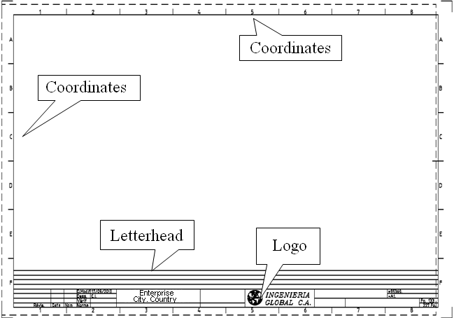
Coordinates, letterhead and Logo
Examples
Two examples of similar drawings below: The first uses European standard (IEC / DIN), and the second uses American standard (ANSI). In both drawings the part of power and control is shown for a three-phase AC motor.
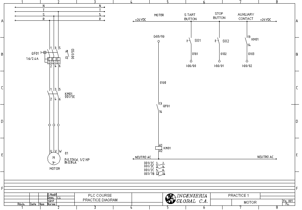
Eurpean standard (IEC/DIN)
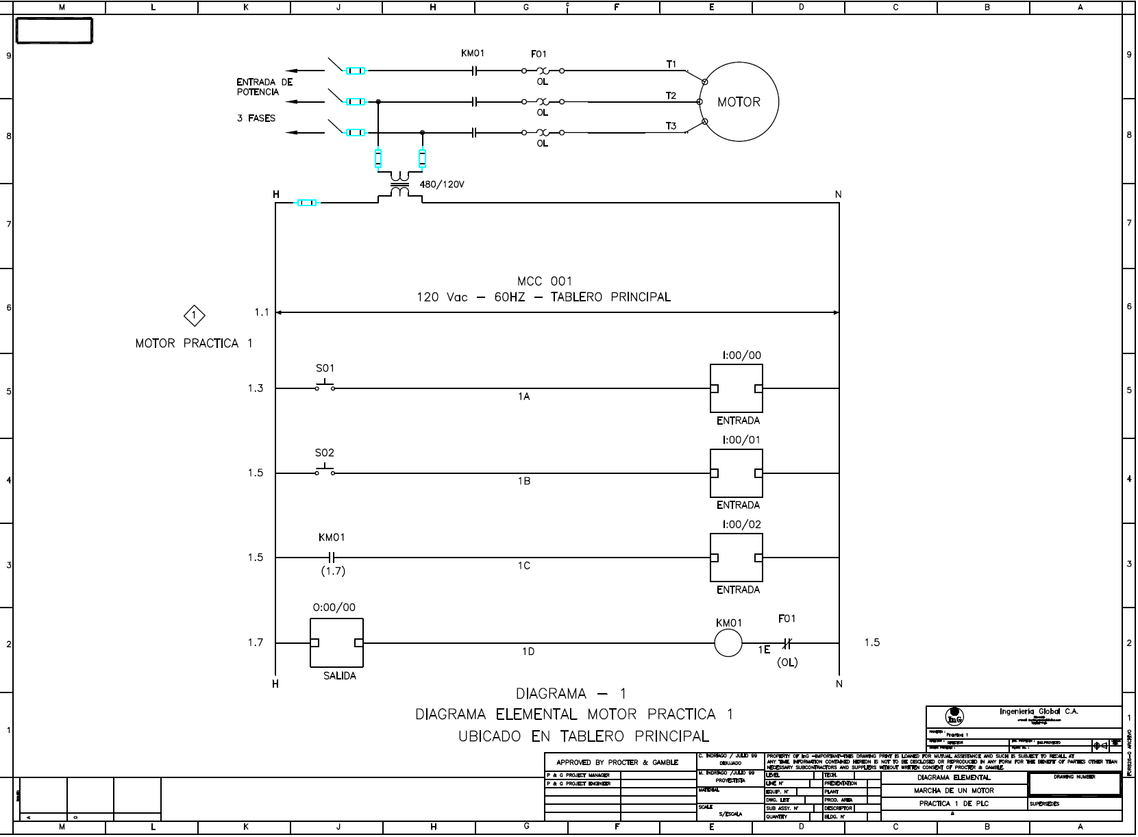
American standard (ANSI)
References
INTERNATIONAL ELECTROTECHNICAL COMMISSION IEC 61082: PREPARATION OF DOCUMENTS USED IN ELECTROTECHNOLOGY, año de publicacion 25 de Enero de 2002